Application US2544443A
1946-06-07
Carl Ingvald Brateng
1946-06-07
Carl Ingvald Brateng
The operation of the device is as follows:
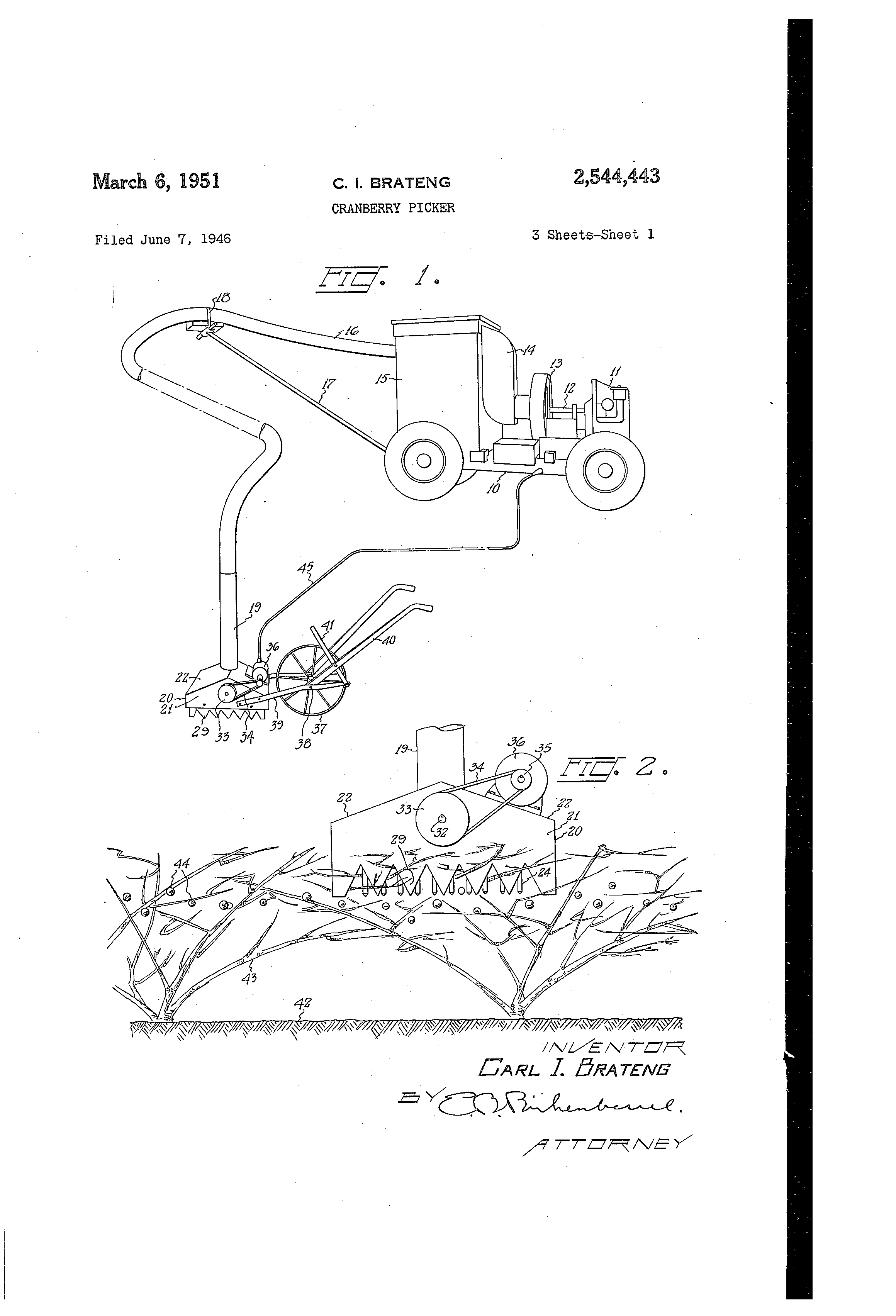
Assuming that the apparatus is in a form shown in Fig. l and that the cranberries are ready `for harvesting, it is only necessary to move the device on its wheel 31, and that it is in a position as shown in Fig. 2, and then by raising up on the handles 40 to permit the device toY settle down upon the brushes from which the berries are to be picked. Power is now supplied to the motor 36 causing the bars 23 to reciprocate and violently shake the berries free from their plants and capable of being picked up by the suction end I9.
It can be seen from the foregoing that there -I will be no tearing of the vines which are held in down on the handles 40 and moving the device to the desired setting.
While I have shown the eccentrics 3| within the box-like structure, it will be apparent that they will function in a similar manner if placed on the outside of the member 20, where they will not be fouled with chaff or any lubricant which is used will not find its way into the fruit.
While I thus illustrated and described my invention, it is not my intention to limit myself to the precise form illustrated herein, but I do intend to cover such forms and modiiications thereof as fall fairly within the appended claims.
Referring in detail to the drawings there is shown a wheeled vehicle I 0,*on which is mounted a motor `I I, whose shaft I2 drives a fan within the casing I3, to which air is supplied by the duct I4, which connects with the separating compartment I5. A suction housing I6 extends from Y the compartment I5 and is supported by the .Y brace I1 which extends from the vehicle IIJ to the clamp I8, which is placed on the housing I6 some distance from the member l5. The housing I6 terminates in a pick-up end I9.
The mechanism thus far described is in common use; its purpose being to pick up the cranberries and deliver them into the separator I5. Referring especially to my invention, same will' 'interior of the box.
The sides yIlI'I are slotted to receive the slidable v'bars 23, from which extend downwardly the Vver-V f tical pegs 24, preferably having their lower ends 25 pointed.V The bars 23 are held in place by their angle members 26 having the points 21 'f formed on'ther downturned sides 28; VThe lower :edges of the ends 2I are also provided with down- ,turned points 29, which are similar in function to the points 21. Each of the l'bars 23 is provided with afpair of anglebars, which are spaced -to receive an eccentric-3l. mounted on a shaft 32 .which Ajournals...in vs lrefu'e'nds 2.I. l l f On thes'haft'3`2 "iswseclred a pulley 33,whose belt 34 passes around the pulley 35 of the drive motor 36 mounted on the roof 22. It is desired to set the eccentric 3I in different positions in order that the positions and travel of the bars 23 be constantly changing with relation to each other.


The second object is to reduce the fatigue ordinarily occasioned by the picking operation.
I accomplish these and other objects in av broken away to show the construction. Fig. 3
is drawn to a larger scale than is Fig. 2.
Fig. 4 is a section taken along the line 4--4 in Fig. 3. n
Fig. 5 is a section taken along the line 5-5 in Fig. 3.
Fig. 6 is a perspective view of one of the aprons. Fig. '7 is a perspective view of the reciprocating bars.


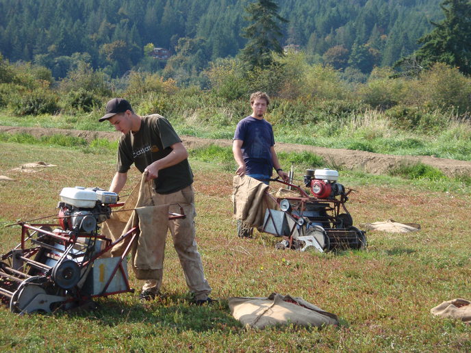
Dry Harvest
https://youtu.be/p0qSpMx1t8o?t=12
https://youtu.be/p0qSpMx1t8o?t=12