Application US340773A
1929-02-18
Wilfred B Mathewson
1929-02-18
Wilfred B Mathewson

The cranberry picker herein shown is of east type wl. h provided with a plurality of connected picking elements carried by a su porting frameadapted to be propelled over the bog arranged to act successively in picking the 1 The suppor ing frame of the construction Serial No. 340,773.
herein shown is indicated generally at l and it is illustrated as a motor-propelled frame, it having the front orsteering wheels 2 and the or d *ing wheels 3. The motive power for propellin the frame is an internal combustion engine 4 which suitably mounted on the frame and which is geared in any usual way to the driving wheels 3. The front Wheels 2 are steering wheels and they are carried in a fork 5 which is swivelled to the front end of the frame and is connected through suitable gearing 161 to a steering rod 6. The frame is provided with a suitable seat 7 for the operator anc. the steering rod 6 has a steering wheel 8 thereon situated within convenient reach of the operator occupying the seat 7.
The picking mechanism is mounted on a supplemental frame 9 which is separate from the main frame 1 and is adjustably supported thereby. The picking mechanism comprises a plurality of picking elements, each in cluding a tined picking member and a scoop or receptacle member. The tined member of each picking element is indicated at 10 and the receptacle member at 11. These picking elements are carried by a rotary carrier which is mounted on the supplemental frame 9 and during the rotation of the carrier the tined member of each picking element is thrust into the cranberry vines beneath the berries, the corresponding receptacle member being at that time separated from the tined member.
After the tined member has entered the vines the two members of each picking elements are closed together and then during the rotation of the carrier the element is withdrawn from the vines thus stripping the berries therefrom. These berries as they are stripped will be retained in the receptacl member until the picking element'has been carried around to the upper portion of the carrier at which time the two members of the picking element are separated to allow the berries to be discharged onto a conveyor which conveys them to a box or other receptacle.
The supplemental frame 9 which carries the picking mechanism comprises two end members which are connected by three transverse members 12, 13, 1 1. Each of these transverse members is in the form of a tube which is clamped at its ends in split bearings formed in the end members of the frame 9. These tie members 12, 18, 14 thus hold the end members of the frame 9 in proper spaced relation and form a rigid structure. The manner of supporting the supplemental frame from the main frame will be presently described.
1.CRANBERRY PICKER Filed Feb. 18, 1929 7 Sheets-Sheet 7 6 Ga P Invenfor Oscar Tcrvo bYM WKM AHys.
Patented Oct. 18, 1932 we sr'rss OSCAR TERVO, OF NORWAY, MAINE, ASSIGNOR '10 WILFRED B. MATHEWSON, OF. NORTH WEYMOUTH, MASSACHUSETTS GRAN BERRY PICKER pplication filed February 18, 19529.
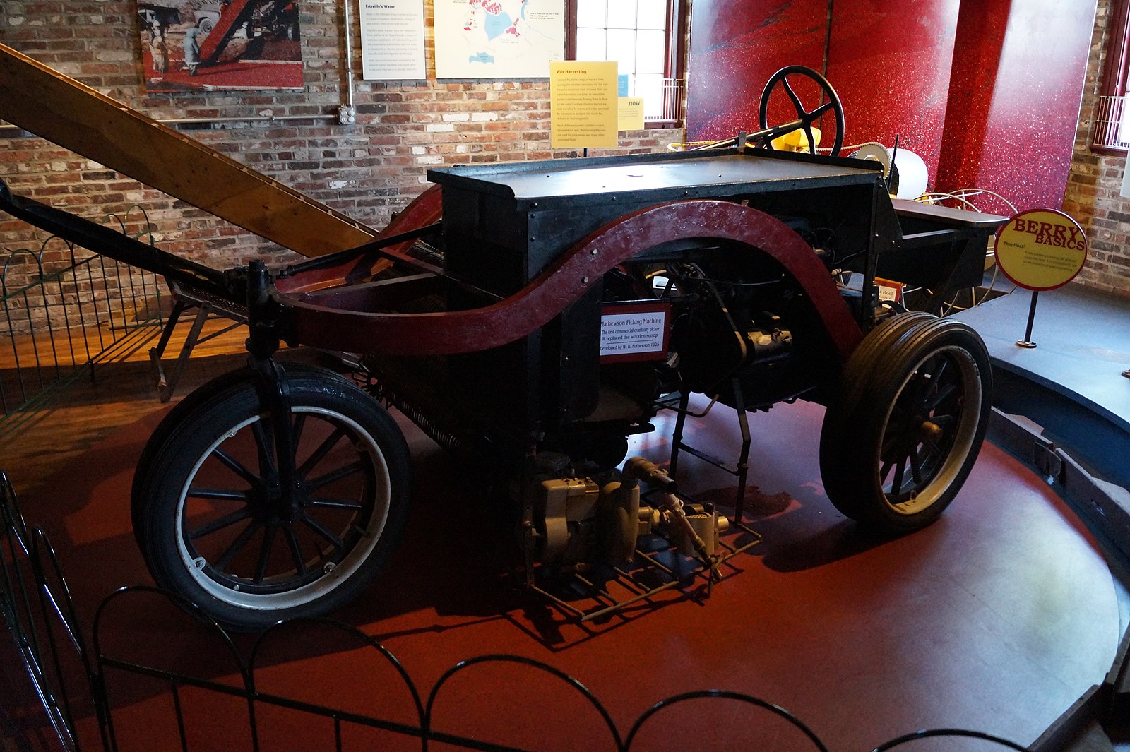

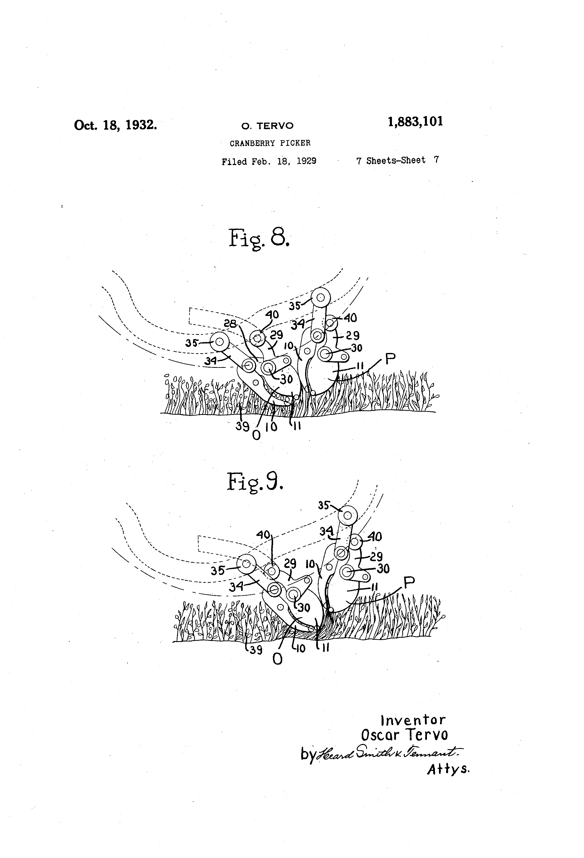
Fig. 1 is a side view of a cranberry picking machine embodying my invention;
Fig. 2 is a top plan view;
Fig. 3 is a fragmentary sectional view illustrating the manner of driving the carrier for the picking elements;
F i is a sectional View of a friction clutch in the main drive;
Fig. 5 is a fragmentary vertical sectional view through the carrier for the picking element illustrating the cams for controlling the picking members;
6 is view illustrating the operation of the cams for controlling the receptacle members of the picking elements;
Fi 7 is a sectional view illustrating the manner of driving the rotatable carrier for the picking element;
F igs. 8 9 illustrate the manner in which the picking elements operate;
Fig. 10 is view of one of the rolls supporting the supplemental frame.