Hand Scoop
1890
Application US550200A
1895-11-19
Alfred M. Shaw
1895-11-19
Alfred M. Shaw
This invention consists of an apparatus for picking and gathering of cranberries from the vines, constructed and arranged for opera tion all substantially as hereinafter fully described, reference being had to the accompanying sheets of drawings, in which is illustrated a cranberry-picker constructed in accordance with this invention.
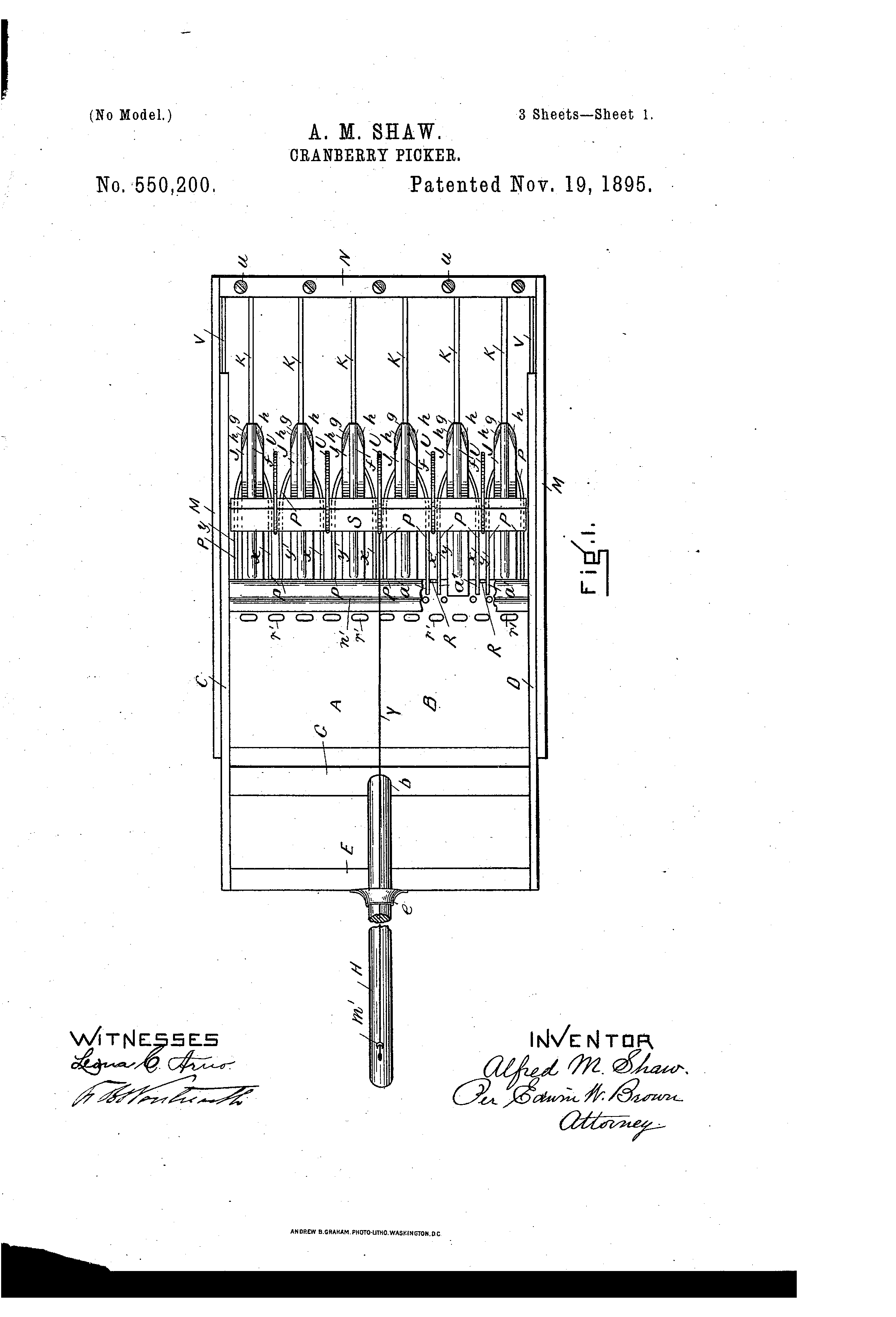
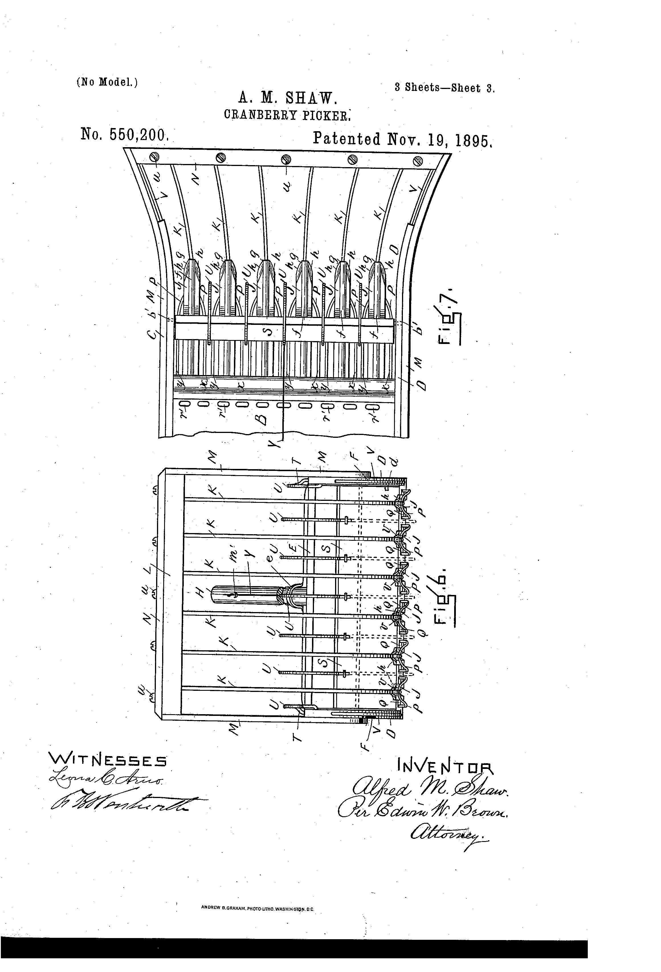
Figure 1 is a plan view. Fig. 2 is a vertical longitudinal central section. Fig. 3 is a detail central longitudinal section similar to Fig. 2, but showing some of the parts in different positions. Fig. 4 is an under plan View of one of the pickers detached and enlarged. Fig. 5 is an end view of Fig. 4. Fig. 6 is a front view, and Fig. 7 is a detail plan view, to be hereinafter referred to.
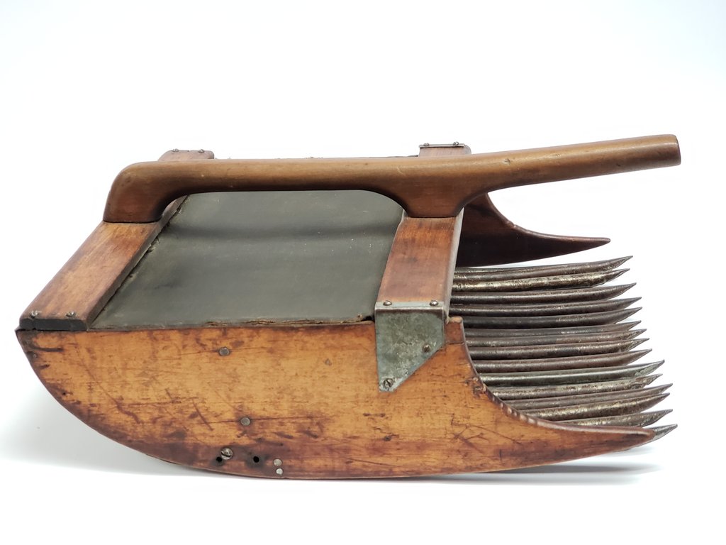
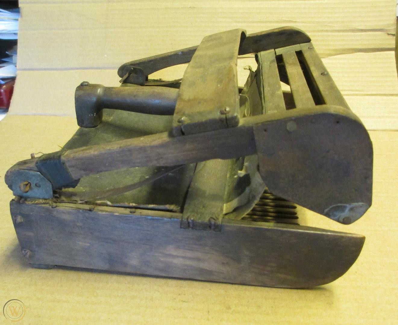
In the drawings, A represents a box or receptacle formed of a bottom B, two sides 0 D, and an end E, its front end and top being open. The two sides 0 D of the box at the front extend beyond the bottom B, and their under edges F, at the front, extend upward in a curved line, as shown at a in Figs. 2 and 3 more particularly. Secured in the box between and to the sides 0 D is a cross-bar G, to which is secured the end 6 of a bar H by a screw cl, which extends upward and beyond the end of the box through a loop e for a handle, the loop being secured to the end piece E. The handle can be removed by unscrewing the screw 01 and drawing it out through the loop, and is readily secured in place again. The sides and end of the box are of wood, but the bottom Bis preferably of sheet metal, and at its front edge are secured by solder a series of pickers or fingers J, preferably at regular intervals laterally, which project horizontally forward and beyond the edge of the bottom, as shown. These pickers are preferably made of sheet metal, and each picker is forced or struck up centrally along its length, as at'fito make a rib, as it were, to give strength to the picker, andits front end is pointed, as at g, as shown in Figs. 1, 4, and
Figure 1 is a plan view. Fig. 2 is a vertical longitudinal central section. Fig. 3 is a detail central longitudinal section similar to Fig. 2, but showing some of the parts in different positions. Fig. 4 is an under plan View of one of the pickers detached and enlarged. Fig. 5 is an end view of Fig. 4. Fig. 6 is a front view, and Fig. 7 is a detail plan view, to be hereinafter referred to.
In the drawings, A represents a box or receptacle formed of a bottom B, two sides 0 D, and an end E, its front end and top being open. The two sides 0 D of the box at the front extend beyond the bottom B, and their under edges F, at the front, extend upward in a curved line, as shown at a in Figs. 2 and 3 more particularly. Secured in the box between and to the sides 0 D is a cross-bar G, to which is secured the end 6 of a bar H by a screw cl, which extends upward and beyond the end of the box through a loop e for a handle, the loop being secured to the end piece E. The handle can be removed by unscrewing the screw 01 and drawing it out through the loop, and is readily secured in place again. The sides and end of the box are of wood, but the bottom Bis preferably of sheet metal, and at its front edge are secured by solder a series of pickers or fingers J, preferably at regular intervals laterally, which project horizontally forward and beyond the edge of the bottom, as shown. These pickers are preferably made of sheet metal, and each picker is forced or struck up centrally along its length, as at'fito make a rib, as it were, to give strength to the picker, andits front end is pointed, as at g, as shown in Figs. 1, 4, and
7, the portion h, each side of the point, being bent downward, as shown more particularly in Fig. 5. A wire K by one end m lies in the groove n, formed on the under side by the forced-up portion f, and it is there soldered to the picker, and from thence it extends upward in a curved direction, as at 'r, Fig. 2, its outer end 25 passing upward through a cross-bar L, extending across and above the box and secured by its two ends to two arms M,'secured, respectively, to the sides of the box, the wires K at their ends being prevented from passing beyond the upper side of the bar L by a strip N, secured on top of the bar by screws u.
The portion m of each wire K where secured to its respective finger is bent downward somewhat, as at o, to form an eye or loop, and to this loop 1: is secured the folded portion w of awire P, the two arms m y of which extend backward, one each side of the picker, the ends a of which are freely disposed in longitudinal grooves or spaces Q, respectively, each side of the picker in the bottom and each arm being stopped in its outward movement by shoulders or blocks R, secured in the groove, as shown more particularly in Fig. 4.
S is a transverse flat board pivoted at b between the two sides, in one of its positions resting against a stop or pin d on the inside of one side of the box, (see Fig. 2,) and adapted to swing freely backward and upward on its pivot and, when desired, into the position shown in section in Fig. 3, where it is stopped and held by a spring-catch T, formed by a wire bent and shaped in a loop form, its two ends being secured, respectively, in the upper edge and side of the box, all as shown in Figs. 2 and 3. Secured to the edge of this swinging board S at intervals by their ends are a series of loops or rings U, of wire, which are of a diameter when the board is in the position shown in Fig. 3 to project forward and down into the spaces e respectively between front portions f of the fingers, there being one ring to each space, as shown in Figssl and 7. When the board is in its position shown in Fig. 2, the rings are up above the spaces and free and clear of them.

1. In a cranberry picker, in combination, a
box or receptacle having its front end open, a series of pickers or fingers secured to the bottom and projecting forward therefrom, a wire or guard secured to the end of each picker and extending forward and upward and secured at their outer ends to a support, and a yielding wire or guard secured to each picker each side there of. I
2. In a cranberry picker, in combination, a box or receptacle having its front end open, a series of pickers or fingers secured to the bottom and projecting forward therefrom, a wire or guard secured to the end of each picker and extending forward and upward in a curved line and secured at their outer ends to a support, and a yielding wire or guard secured to each picker each side thereof.
3. In a cranberry picker, in combination, a box or receptacle having its front end open, a series of pickers or fingers secured to the bottom and projecting forward therefrom, a wire or guard secured to the end of each picker and extending forward and upward, and a yielding wire or guard secured to each picker each side thereof.
4. In a cranberry picker, in combination, a box or receptacle having its front end open, a series of pickers or fingers secured to the bottom and projecting forward therefrom, a yielding guard each side of the picker formed of wire folded upon itself and secured by its folded portion to the picker at or near its end.
5. In a cranberry picker, in combination, a box or receptacle having its front end open, a series of pickers or fingers secured to the bottom and projecting forward therefrom and a yielding wire or guard secured to each picker each side thereof.
6. In a cranberry picker, in combination, a box or receptacle having its front end open, a series of pickers or fingers secured to the bottom and projecting forward therefrom, a wire or guard secured to the end of each picker and extending forward and upward and secured at their outer ends to a support, and a gate or board pivoted within the box or receptacle provided with rings or loops or projecting strips to extend into the spaces between the fingers or pickers and adapted to be secured in its open position.